Giga Tool Head Assembly
Thanks for purchasing the toolhead upgrade! This intends to be a comprehensive install procedure
Step 1- Prep
1-1
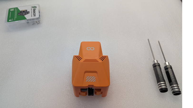
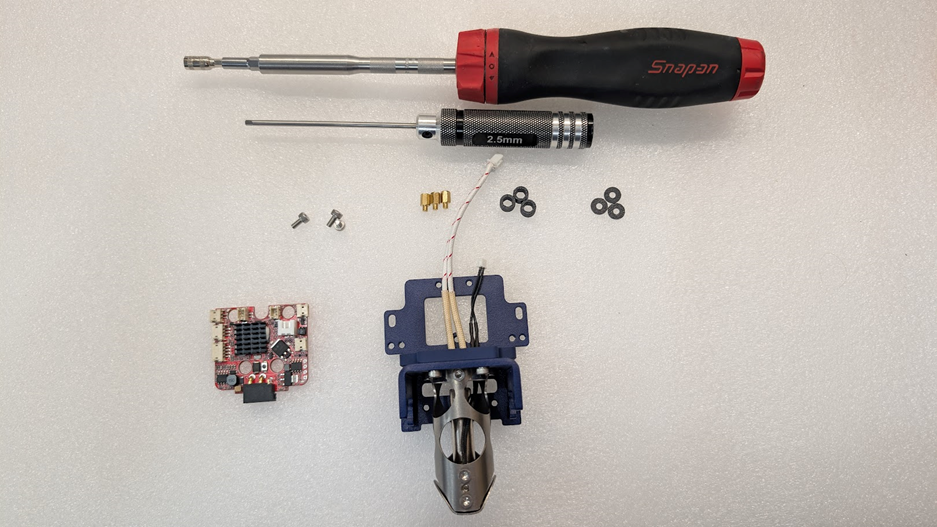
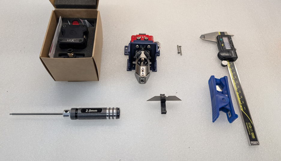
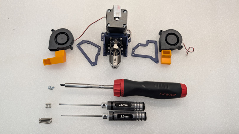
First things first, we’re going to need some tools to complete this tutorial. The tools required are as follows.
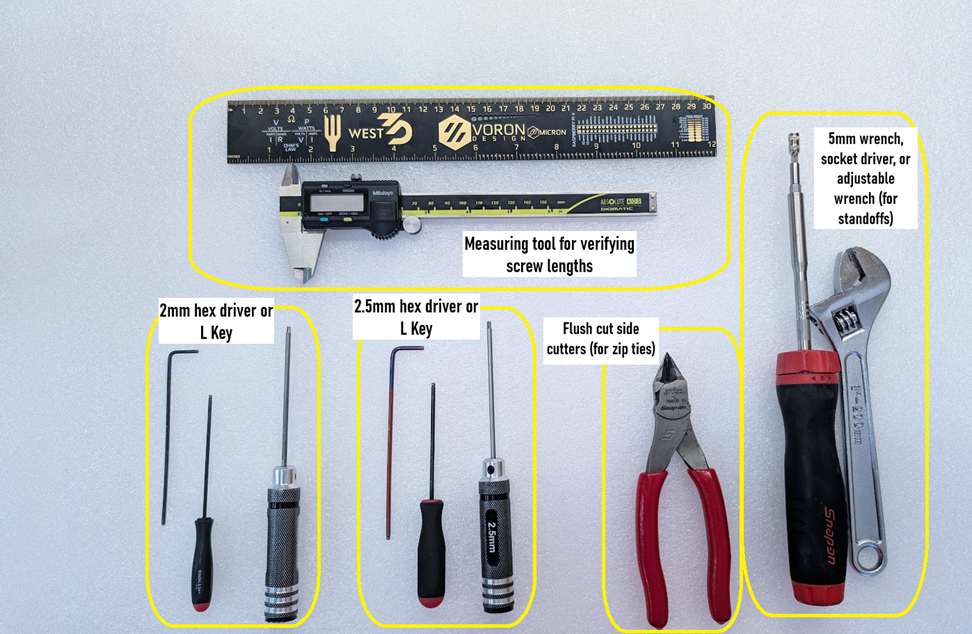
2mm and 2.5mm hex driver- We would recommend a driver with a thin shank or extended length L key, as this will assist when trying to get at screws in hard-to-reach places.
Measuring tool- We will be using different length screws, so it helps to have a measuring tool like a set of calipers or a metric ruler to assist with checking this.
Flush Cutters- When routing wires, we’ll want some flush cutters to trim zip ties flush so they aren’t sharp. No one likes getting cut on zip ties!
5mm wrench, socket, or adjustable wrench- When installing standoffs for the tool board, we want to ensure they’re nice and tight so they don’t come loose later.
#1 Phillips driver (not shown)- This is for the screws on the fan ducts
Tubing cutter, or cutting jig and razer (not shown)- this is for cutting your PTFE tube to the correct length for the extruder
1-2
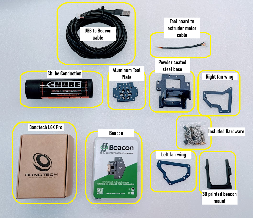
Next, we’re going to want to verify we have everything we need for this upgrade. Parts needed are as follows
- Chube Conduction w/ heater and thermistor
- Bondtech LGX pro
- Powder coated steel base plate
- Left and right fan wings
- Aluminum tool place
- Hardware kit
- 3D printed Beacon Mount
- 5m USB to Beacon cable
- Tool board to LGX extruder motor cable
1-3
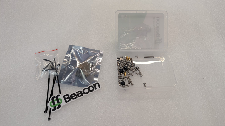
It’s helpful to have a clean and organized place to work, so we recommend clearing a large flat space on a work bench or desk for assembly. It can also help if you put the screws in the hardware kit in a shallow try to make it easier to keep track of them and pick out what you need. The case from the beacon works excellently for this purpose.
Step 2- Disassembly
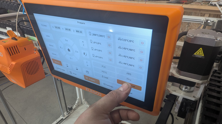
2-1- Unload filament
Next we’re going to need to get the old tool head off your machine. First you’ll need to unload the filament. You can start this by heating up the hotend to the temp required for the filament that’s loaded and unloading the filament using the unload button in the prepare tab on the screen.
2-2- Removal of tool head
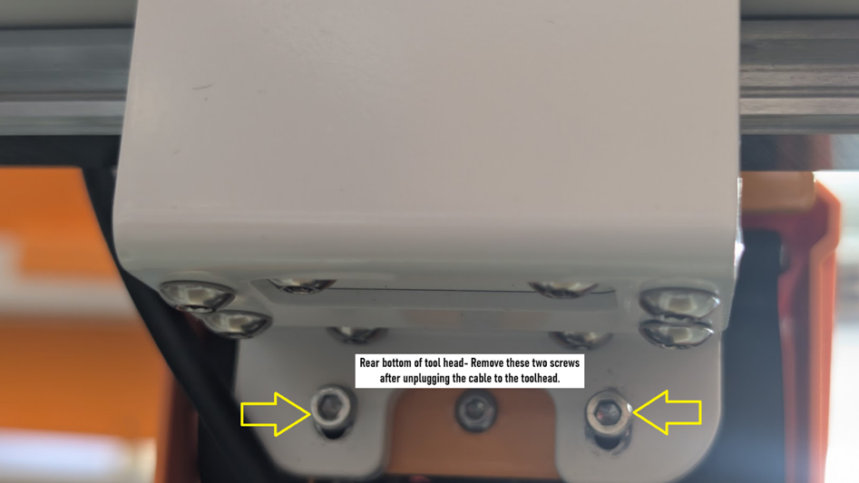
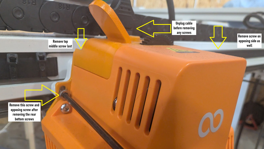
After unloading the filament, next step is powering is powering off the machine. It’s best not to remove the previous toolhead under power. Once powered off, there are 4 screws, and one plug that need to be removed as shown below. Remove the rear bottom screws first so you can hold the tool head in place Save these screws, as they will be reused to re-install the updated tool head.
Bring the removed toolhead to your work area for disassembly-
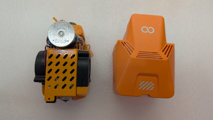
2-3- Tear down of stock hotend.
Now that we have the stock toolhead where we can work on it easier, we will need to tear it down for the parts we need to reuse. This consists of the toolboard, and the left and right part cooling fans as well as their ducts.
-Remove the two screws on the front of the shroud
-You can now remove the plastic shroud around the tool head
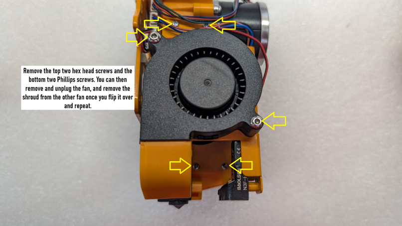
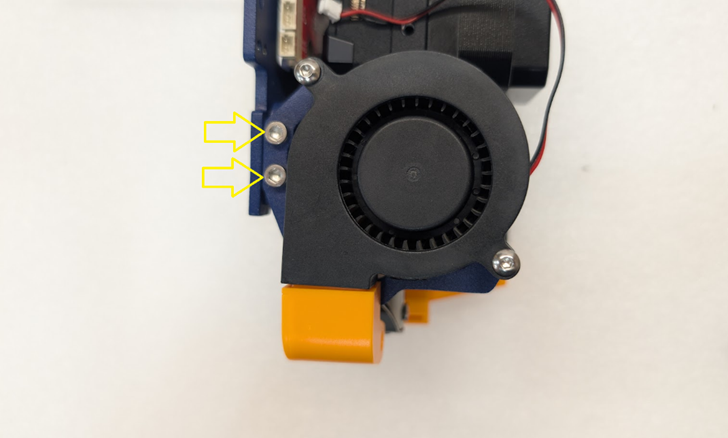
-Turn over onto right side and unplug the fan and then remove the two hex head screws, followed by the two phillips screws under it for the opposite side fan shroud. Last, remove the top left and right Philips screw for the metal frame Save the Philips screws- we will reuse them.
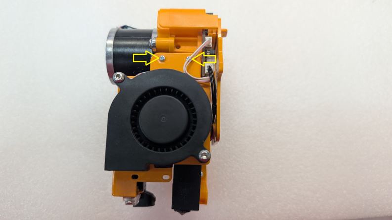
Flip over the toolhead onto it’s right side. In order to get at the screws for the left fan shroud we will need to remove the two top Philips screws that hold the metal shroud over the hotend first.
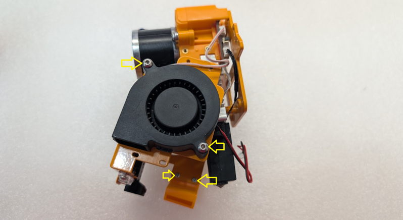
With those screws out, we can now pivot the shroud outward to gain access to the fan shroud screws on the left side, and we can remove the screws for the right side and unplug/remove the fan.
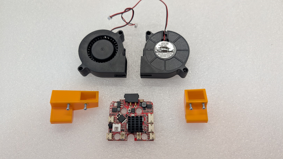
With
the fans and fan shrouds removed, all that’s left to save is the tool board.
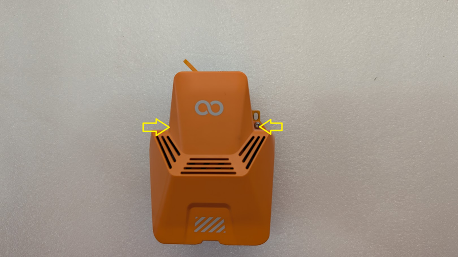
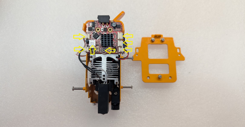
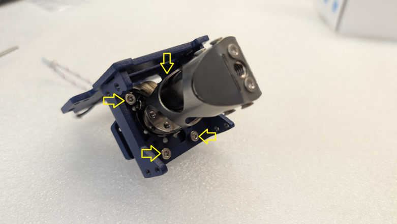
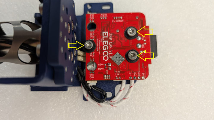
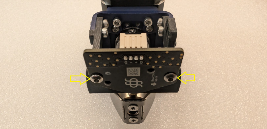
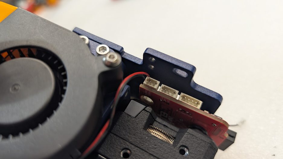
Flip the toolhead over onto it’s face and remove the 3 hex head screws shown
here and remove the rear plate with the tool board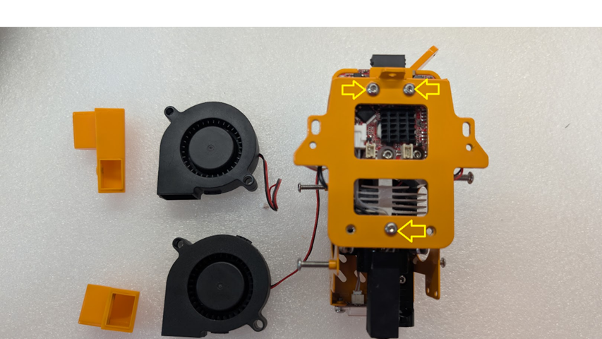
Next, unplug all plugs on the tool board, and remove the single hex head screw holding the board in place. You can now remove the tool board.
You can set the remainder of the original toolhead aside. We’d recommend reassembling it without these parts and setting it somewhere safe in case you ever need spare parts later.
Step 3- Toolhead Assembly
3-1- mount the chube onto the aluminum tool plate
Tools needed- 2.5mm hex head driver or L key
Parts needed- Aluminum tool plate, 6 M3x0.5x8mm socket head screws, Chube Conduction, and (optionally) thermal grease.
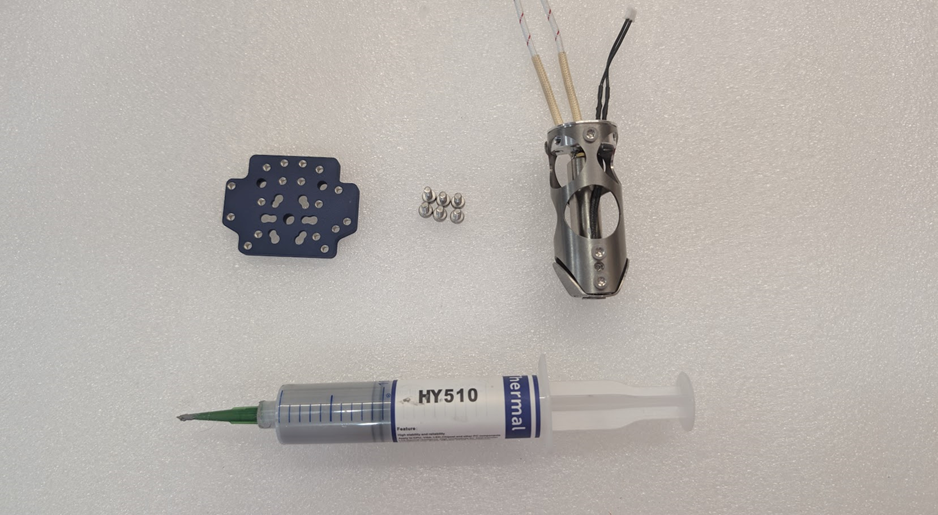
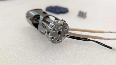
Install Chube onto the tool plate with the 6 socket cap screws. Pay close attention to the wires, the orientation of the tool plate (screw heads should sit inside the counterbores), and the wires (should be pointed to the back of the tool plate). Review the picture for advice
Bend the wires straight up once assembled as shown. This will help in the next step and allow the hotend to install easier without fighting the wires.
3-2- Installing hotend assembly onto the steel base
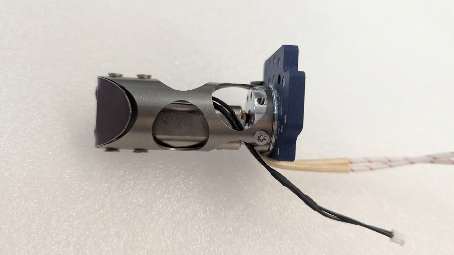
Slide chube down through the top of the steel base with the wires facing to the back of the base. Secure with 4 socket cap screws from the bottom.
3-3- Installing the tool board
Tools Needed- 5mm socket drive or wrench, 2.5mm hex driver or L key
Parts Needed- 3 M3x0.5mm standoffs, 3 M3x0.5x5mm screws (socket or button), 3 3d printed bushings, 3 3d printed washers (DO NOT use metal washers for this application, as they could lead to shorted components), the original giga toolboard, and the hotend assembly so far.
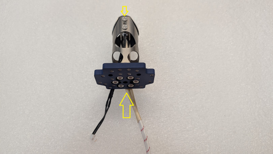
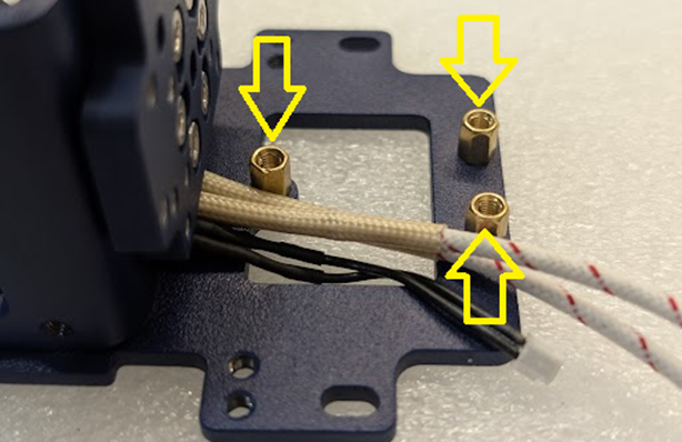
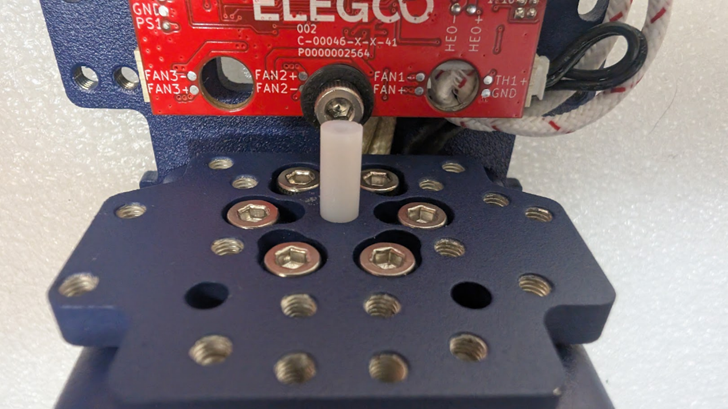
Install the 3 M3 standoffs for the toolboard. Get them all finger tight and tighten no more than 1/8th of a turn using a 5mm socket, wrench, or adjustable wrench. Anymore than that and you will risk shearing the threads on the standoff due to them being brass. You can route the wires to the right of the standoffs as pictured.
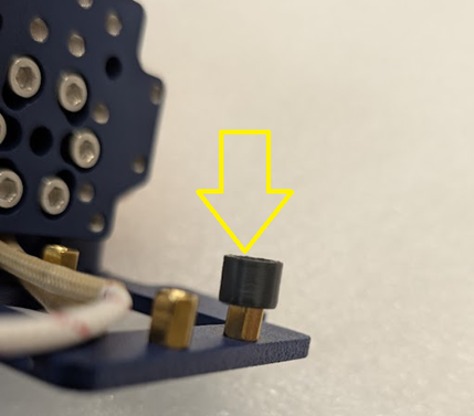
Once the standoffs are installed, we need to install the 3 3d printed bushings. These are press fit, so they may take a small amount of force, but shouldn’t require an excessive amount. Bushings should sit flush.
Once standoffs and bushings have been prepared, it’s important to plug the heater into the giga toolboard now before installing, as you will not be able to access this plug when installed.
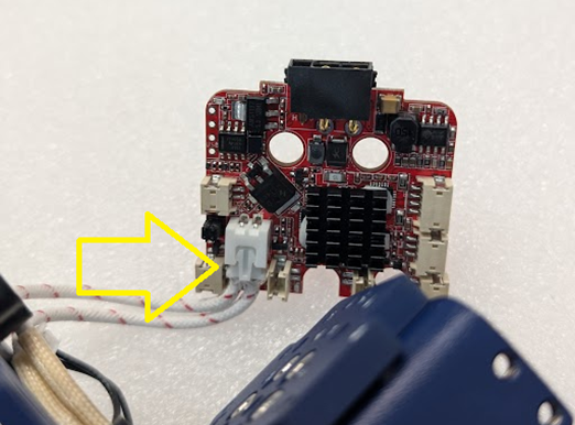
When installing the board, VERY CAREFULLY curl the heater cable in a loop like so while not putting any force on the crimped connections- be warned, too much back and forth movement at the crimped connection CAN break the wires free from the crimp.
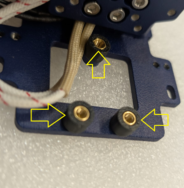
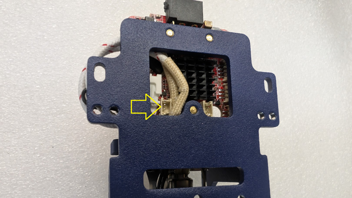
Before plugging in the thermistor, fasten the board in place using the 3 m3x0.5xm5 screws with the 3 3d printed washers as pictured. Be sure to make sure the fan port on the rear of the board is still accessible before tightening the board all the way for later steps, and make sure to not over-tighten the screws.
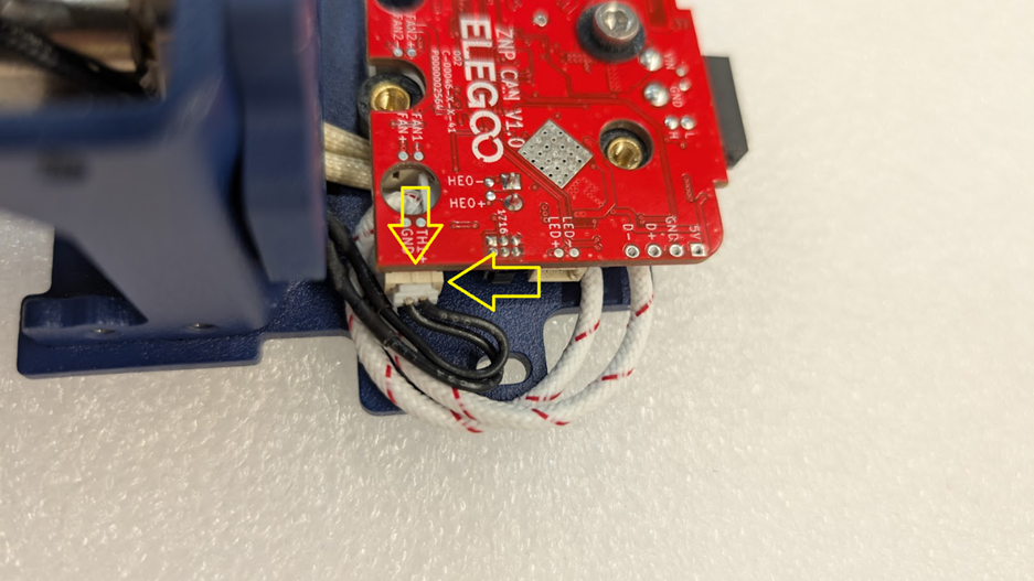
You can now plug in the cable for the thermistor; this will plug in to the terminals labeled TH1+ and GND on the board. You can route the cables in line with the heater cable to keep things neat as shown.
3-4- Installing the extruder
Tools needed- 2mm hex driver or L key, (option 1) 3d printed PTFE tool jig and razor blade, (option 2) calipers/tubing cutter.
Parts needed- Bondtech LGX Pro extruder, 2 M3x0.5x20mm screws, and the toolhead assembly so far
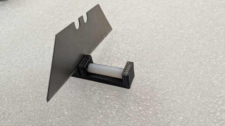
First thing we’ll need to do, is take the PTFE tube included in your LGX Pro extruder box, and the PTFE tube will need to be cut to 19.5mm. This can be achieved by either using the jig we have available for download HERE on our github (as shown here), or using a set of calipers to measure and a normal tubing cutter.
Once the PTFE tube is cut to length, insert it into the top of the chube through the aluminum mounting bracket.
Once the PTFE is seated into the Chube, you can use the PTFE tube to line up the LGX Pro and seat it in place as shown.
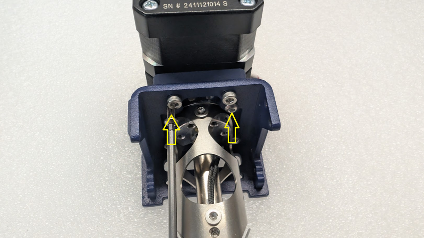
Seat the extruder all the way in place, and from the bottom, insert the two 20mm m3 screws and secure the extruder to the assembly.
3-5- installing the Beacon
Tools Needed- 2 and 2.5MM hex driver or L key
Parts
needed- Assembly so far, beacon 3d printed mount, Beacon scanner, 2 M3x0.5x8MM
BUTTON head screws (it is important that these are button heads), 4 M3x0.5x6MM
socket head screws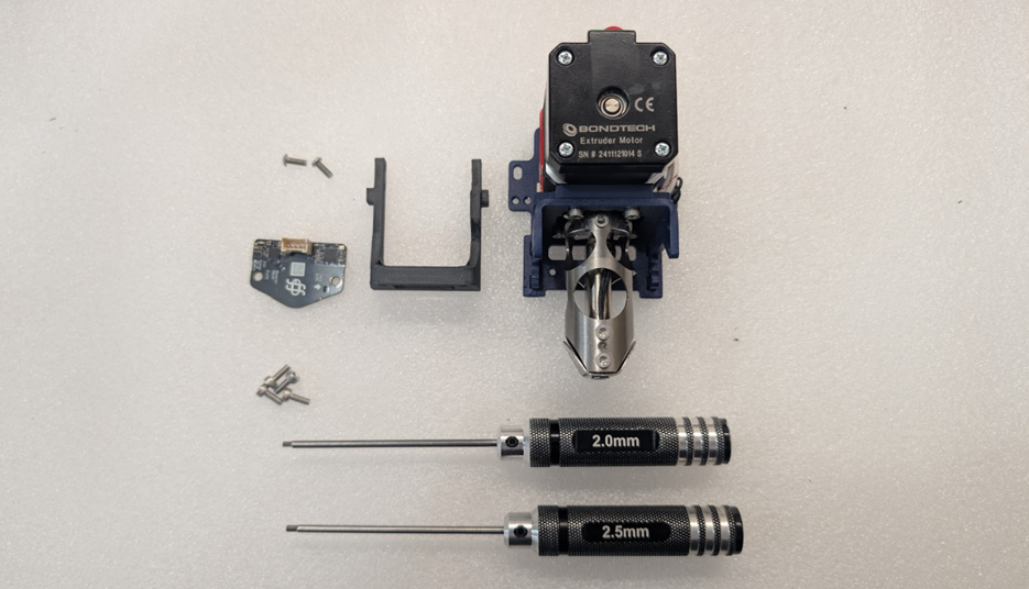
Installing the beacon mount- Insert 2 of the M3x0.5x6MM socket head screws from the INSIDE of the mount, it can help to screw these in using a ball ended 2.5mm hex L key or driver.
Installing the beacon- Use the 2 M3x0.5x8MM BUTTON head screws to install the beacon to the bottom of the beacon mount. It is important to use the correct button head screws, as the two screws that are included in the beacon kit are too short, and a socket head may protrude too far and interfere with the beacon scanner.
3-6- Installing the fans
Tools Needed- #1 phillips driver, 2mm and 2.5mm hex driver/L key
Parts needed- Assembly so far, left and right fan wings, left and right fan ducts, left and right fans that we took from the original toolhead, 4 phillips head screws we took from the original toolhead, 4 M3x0.5x8mm socket head screws, 4 M3x0.5x20mm button head screws
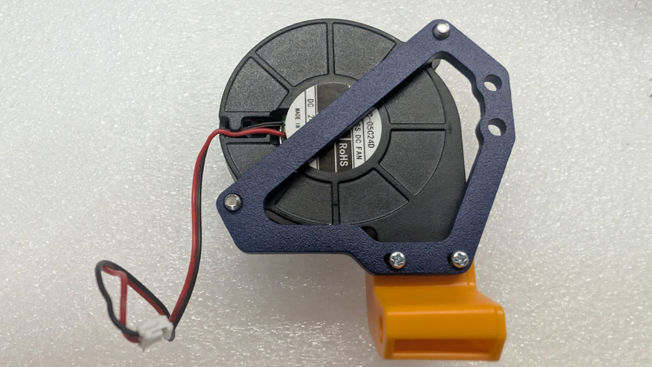
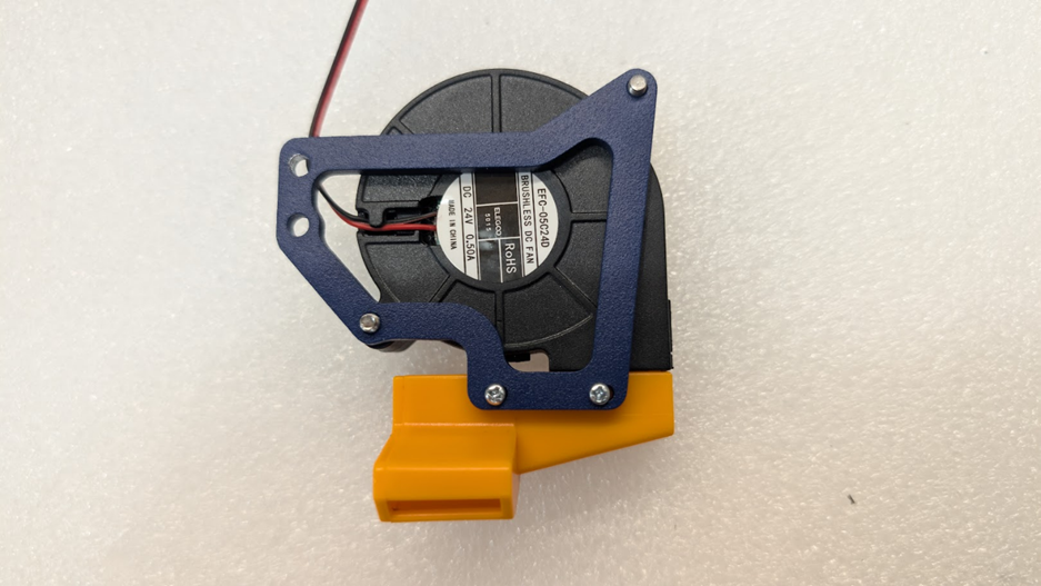
On the left and right wings, begin by placing the fans on them and installing them with 2 M3x0.5x20MM screws each
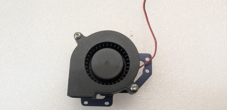
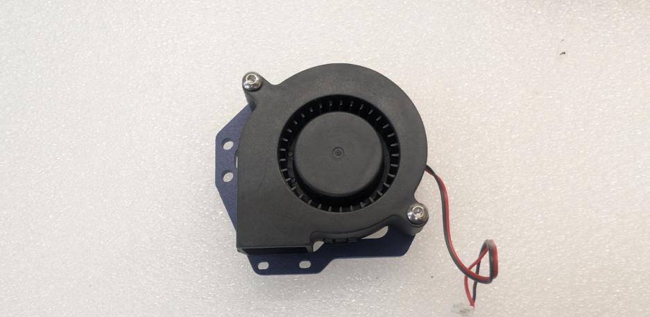
Once the fans are installed on wings, we can then install the ducts using 2 of the Philips head screws on each with the screws mounting from the other side of the wing.
Now we can install the ducts on either side of the assembly using 2 M3x0.5x8MM screws on both sides
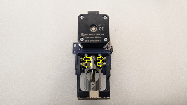
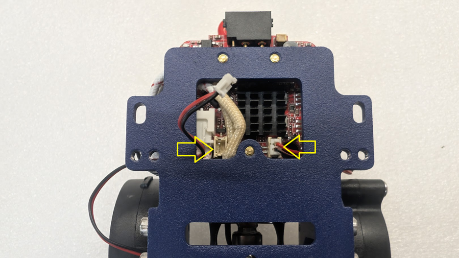
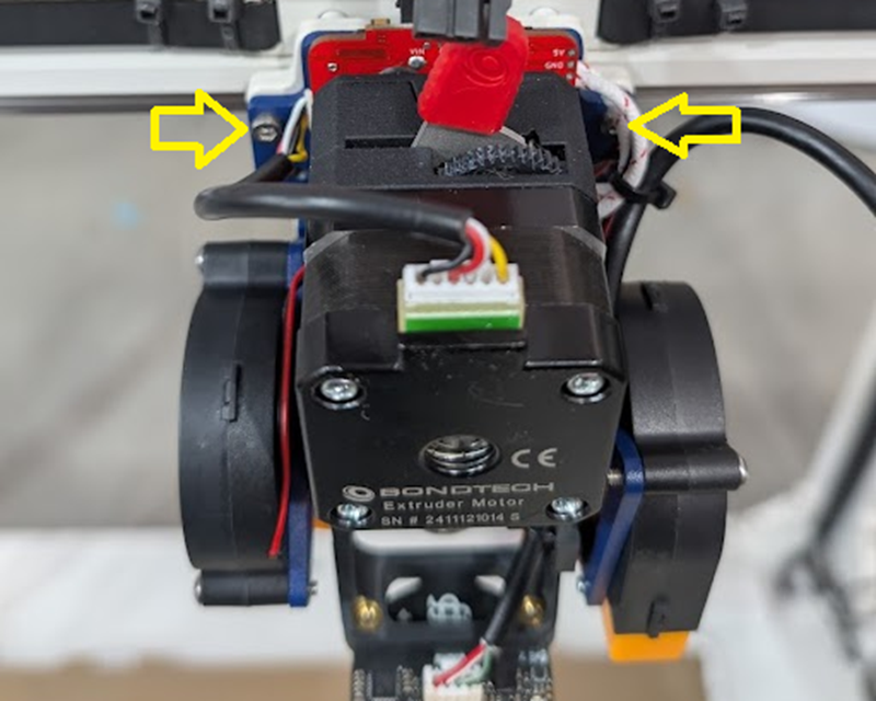
Once the fans are installed, we need to route the wires. It is important that the wires are routed between the steel and the toolboard, and NOT behind the steel, as they will interfere with mounting the toolhead to the machine. You can then plug in the fans to the ports shown
3-7- Wiring
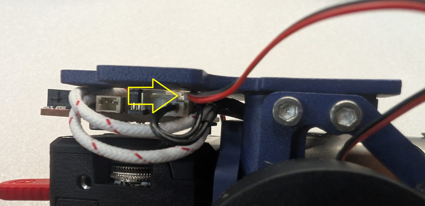
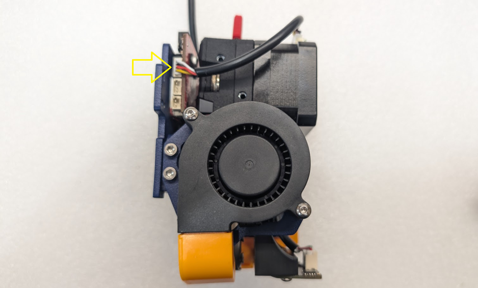
You can start by plugging the beacon cable into the beacon as shown here.
Next, you can zip tie the cable to the cabletie slots built into the mount. If you have trouble feeding the zip tie, you can temporarily remove the right side fan as shown.

Cut off the zip tie flush, and now we can route the cable up through the right side of the toolhead and zip tie it in place along with our other cables going to the tool board to make it nice and neat. Cut this tie flush as well.
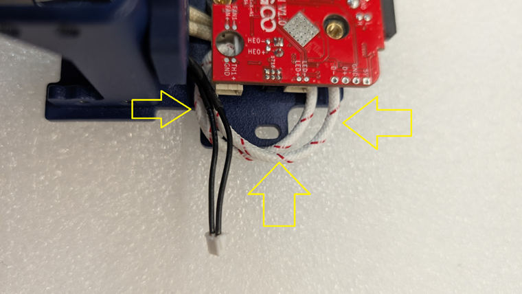
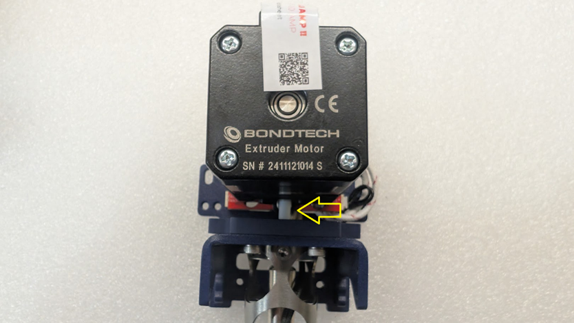
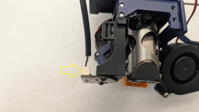
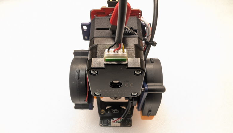
Now that the beacon cable is mounted, we can install the extruder motor cable by plugging it first into the top of the motor shown here
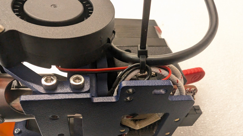
Now route the motor cable down the left side of the motor and we can plug it into the tool board here
Congrats!
Your toolhead is now assembled and ready for install on the machine.

Step 4- Installation
4-1- Installing the toolhead to the machine
Now that our toolhead is assembled, it’s time to get it on the machine so we can get printing. You can start by lining it up with the carriage and putting the two original bolts through the toolhead like this
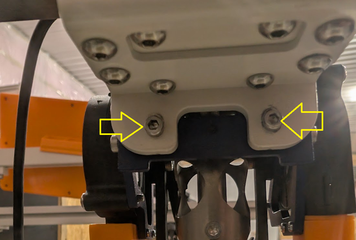
On the other side of the toolhead at the bottom, reinstall the two original screws from the original toolhead here
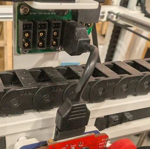
And finally, you can plug in the original tool board with the original canbus cable
4-2- Routing cables
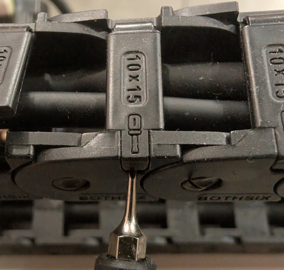
Taking a very small flathead screwdriver, you can now start unlatching the latches on the cable chains all the way back to where the toolhead is plugged in at the base of the machine and run the cable for the beacon. Take your time with this, you’ll be on this step for awhile.
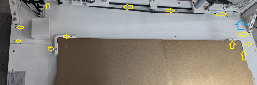
Once the cable is finally routed to the bottom right machine, you now have two options, you can either route the cable to the blue arrow in the bottom picture and plug it in there, or, for the cleanest look, you can remove the bottom pannel by removing all the screws on the bottom panel marked by the yellow arrows and, unplugging all the cables from the IO corner, and pulling the panel free to have access to the mainboard.
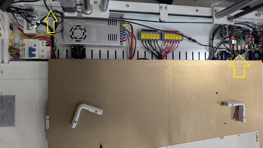
You can then run the cables through the bottom panel to the board, unplug your choice of usb extension cables (either to the usb at the blue arrow, or to the usb that’s mounted on the front of the machine) and plug the beacon in there. Make sure when you route the cable that you run it alongside the Z motor cable closest to the IO corner.
Once the panel is reassembled if you ran the cable that way, your toolhead is now fully installed. From here, the remainder of this upgrade will be finished on the software side of things.